MAKE CENTAUR SOUND BIG AGAIN
In the early 1980's Pinball was going through it's heyday with the early electronic machines that used digital sound effects and speech synthesis to their full in giving the games an electronic persona. One such machine was Bally's Centaur which had one extra feature that no other machine (apart from Centaur II) was made with, an auxilliary circuit board that added echo/reverb to the speech and sounds. While this might not sound too remarkable, it was actually quite unusual to have fully solid state echo circuitry round about that time and the effect was very appropriate for the thunderously deep speech and the image of the machine. Unfortunately the system used a specialist guitar reverb chip called a SAD4096 by Reticon. It was appropriately named since SADly these chips are inherently prone to failure over time and most Centaurs still in existence don't have a working echo module.
Since I have a particular liking for the older electronic pinball machines I ended up with a Centaur in my personal collection of machines and predictably it's echo circuit was duff. I duly removed the "Say It Again" board (that's actually what it's called) and designed an alternative that could utilise the existing connectors and fixings to act as an easy retrofit. This page contains all the data needed including the PCB foils in TIF format to allow you to build one too. I should add that since it's taken me a while to get round to putting this on my website, the availability of the specified Holtek echo chip and even the RAM chip is a bit dubious. The speed of technological progress is such that chips seem to go obsolete quite quickly, however, the chips may be able to be sourced from specialist repairer supply companies.
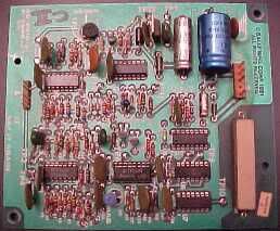
This is the original double sided "Say It Again" board out of a Centaur. In this case it's marked with CII suggesting it's been a substitution unit from a Centaur II machine (mine is an original Centaur).
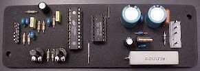
And here's my single sided alternative unit that was optimised to use the minimum number of components as possible as is my general design style. It uses two of the original board fixings and is fully compatible with the original connectors. Since it's a more modern board I decided to improve on the original unit by offering the option of a much longer echo delay, which gives an extra dimension to the machines sound effects.
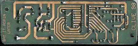
The back of the PCB has been designed using Chunky-Trax technology to make the board easier to etch for anyone wanting to make one themselves from the artwork files included at the bottom of this page.
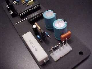
This is the power supply end of the board and uses the original design of the power supply section of the SIA board. It derives the 5v supply from the 43v supply via a drop down resistor with various levels of smoothing. It then regulates the supply down to 5v for the sound processing circuitry. The current requirement of the new circuitry is only about 20mA, so a much higher value of resistor can be used which also means less heat dissipation.
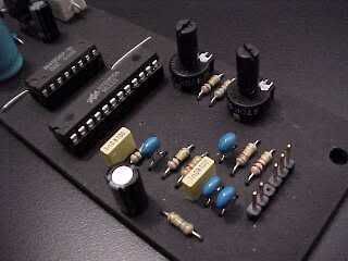
At the business end of the board a Holtek HT8955 echo chip uses a 41256 DRAM chip as a large FIFO register to create a delay using firstly analogue to digital conversion, then digital to analogue conversion. The incoming audio signal from the Squawk & Talk board is decoupled and applied to the input of the HT8955 where it is amplified using a built in op-amp with both simple filtering and preset gain set by the external negative feedback resistor. The output of the op-amp feeds the echo circuitry but is also used as the output back to the Squawk & Talk boards amplifier with a bit more filtering and a set voltage divider to ensure the correct signal level. The delayed echo output is fed back into the input via a control potentiometer that sets the level and therefore number of repetitions, while the rate of the echo is controlled by another potentiometer that forms part of an integral oscillator. Another fixed oscillator controls the sampling speed.
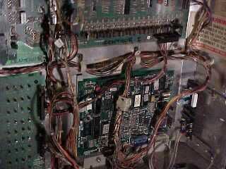
Here's the board in situ at the lower right hand side of the backbox.
If you want to make one of these units then I would initially suggest that you source the two main chips first since I fear they may have already gone in the direction of obsoletion. I'll keep a look out for a nice sensible echo chip that doesn't need a squillion capacitors and resistors surrounding it's every pin, with a view to a design update.
If you can get the chips then here are the files in TIF format to make your own PCB's. If you view the images directly they will look a bit ragged at the edges. This is because they have been scanned from a laser printed original, but when they are printed at 300DPI the image will be fine. I chose TIF because it seems to carry information that results in printing being done at the correct size. If you don't have the ability to read the TIF format on your computer then you might take a look at the Irfanview website where you can download a freeware file viewing utility.
There are two files, namely:- echotrax.tif which is the copper layout, and echoface.tif which is the silkscreen top of the PCB showing component layout. On the copper artwork a 0.5" scale has been printed on the X and Y axis to allow validation of printout accuracy. These are the files:-
Click here for the track layout in TIF format
Click here for the component layout in TIF format
The component values for the PCB are as follows:-