CONVERT OLD TUNGSTEN CHRISTMAS FAIRY LIGHTS TO LED.
This project involves taking traditional push-in tungsten lamp Christmas lights (or fairy lights as we call them in the UK) and converting them to LEDs.
This reduces their power consumption considerably and lets you use ANY colour of LED you can find to make up custom sets of lights. And you can change them for new LEDs at any time because they use standard LEDs.
This project involves mains voltages capable of dissipating all Christmas cheer instantly and potentially burning down your festively decorated home (including the tree and all the presents thereunder) so only build it if you have good competence at working with mains voltages. As with all projects on this site you do the project at your own risk.
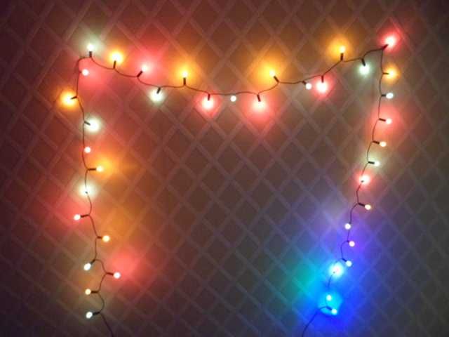
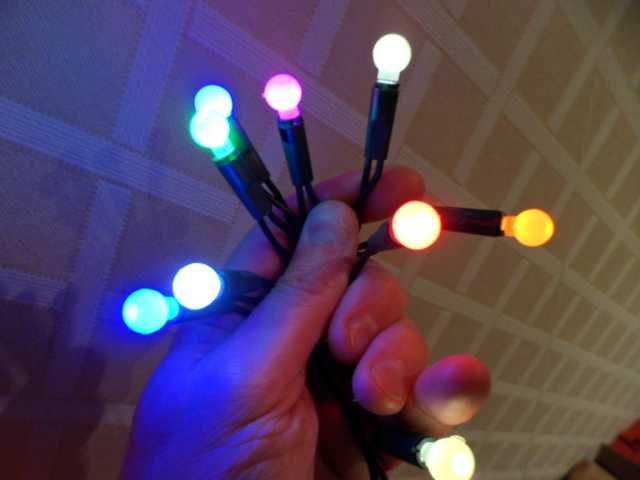
This is what we're aiming for. A bright string of changeable LEDs that can be modified and customised to your hearts content. My camera has been quite generous with the intensity in this picture. The LEDs are deliberately run at low intensity to give them a gentle tungsten-like glow and keep the in-line power supply as simple as possible.
In this particular string I alternated red, orange and warm white for a traditional tungsten look, but couldn't resist adding a spectrum of colours at one end. The LEDs actually have little round push-on berry covers to diffuse them.
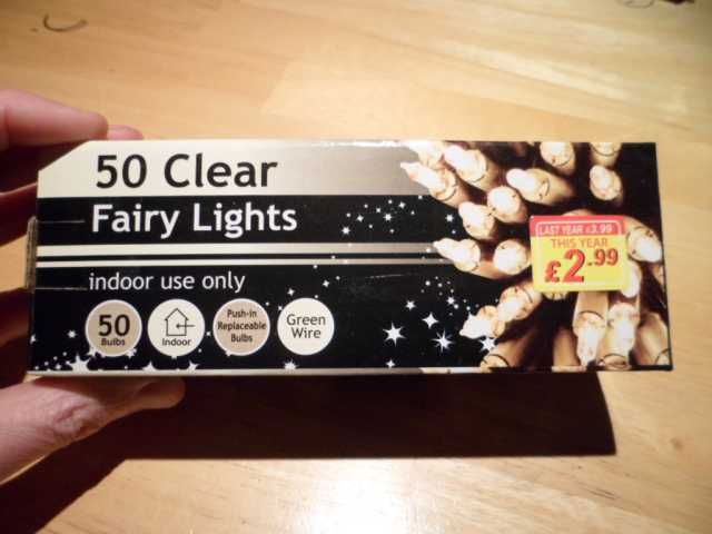
This is the type of set we are looking to modify. The lights should be a continuous single string, and the number that can be used depends on your mains supply voltage.
In the UK and Europe we have a 230V mains supply which means we can run quite a lot of LEDs in series. A typical string will have about 40 or 50 LEDs in series giving a total string voltage of about 80 to 150V depending on the number and type of LED, although if a smoothing capacitor is used a higher number of LEDs can be used.
In countries like the USA where the mains voltage is around 120V a smaller number of LEDs can be used in the region of 20 to 30. Most push-in sets have a simple strain relief and contact system that allows sets to be shortened or lengthened for custom numbers of LEDs.
Do not use less than 40 LEDs on a 230V supply, or less than 10 on a 120V supply as it will result in excess heat in the power supply resistors.
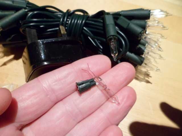
This project is only suitable for sets of lights that have push in lamps where the glass lamp is not glued into the base. The set must have mains rated wiring for safety reasons.
If we just changed the original tungsten lamps to LEDs they would probably be destroyed almost instantly as LEDs are only suited for a limited DC current.
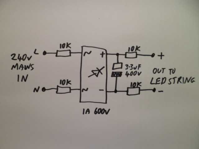
The power supply circuit shown above is about as simple as possible. There are just a few resistors to limit the current and a bridge rectifier to convert it from AC to DC. I've also shown an electrolytic capacitor in the schematic above and its function was to reduce the slight flicker caused by the unsmoothed mains supply, but latterly I decided it's better not to use it as there is a remote possibility that it could fail short circuit and overload the two resistors between it and the mains.
The resistors are chosen to limit the current to a few milliamps and as such their combined power rating doesn't have to be very high. The bulk of the mains supply voltage will be dropped across the LEDs with the rest being dissipated as heat from the resistors.
For a 230V mains supply it's best to use a minimum of 40 LEDs which will typically drop around 2.5V each giving a total of about 120V. This leaves 110V to drop across the resistors. I used four 10K ohm (ten thousand ohm) quarter watt resistors giving a total of 40,000 ohms. That gives a theoretical current of around 3mA which means that means that just 0.33 Watts is being dissipated from the resistors, or less than a tenth of a watt from each.
For a 120V supply with 20 LEDs we would have about 50V across the LEDs and 70V to drop across the resistors. So we could use four 4700 ohm quarter watt resistors which would again give about 3mA through the circuit and dissipate less than 0.1W across each of the four resistors.
The use of four resistors is for thermal and electrical safety, since spreading the dissipation across four results in lower heat (barely body temperature) and the multiple resistors also increases their combined voltage handling. It also just so happens that the rectifier has four leads and it's really easy to just solder a resistor on each lead so they all end up in series with the current path even if it looks a bit weird on the schematic.
The rectifier should be rated for at least the peak mains voltage. It won't see that voltage in normal operation, but when LEDs are removed from the circuit the voltage can go up to peak mains voltage. For a 230V supply I recommend a rectifier rated at 1A 600V and for a 120V supply I recommend a rectifier rated 1A at 200V. The 1 Amp rating is WAY more than is needed by a huge margin, but it's a very common rating of rectifier. You can make a discrete rectifier from four 1A diodes, but I recommend using a bridge rectifier for simplicity.
Now how simple is this? Ignore the capacitor, since it's probably better not to use it, and the high voltage ones are quite hard to find anyway. The circuit only need the four resistors and the bridge rectifier.
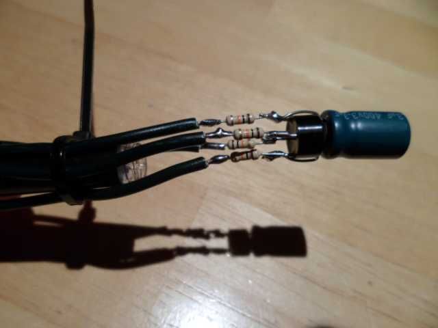
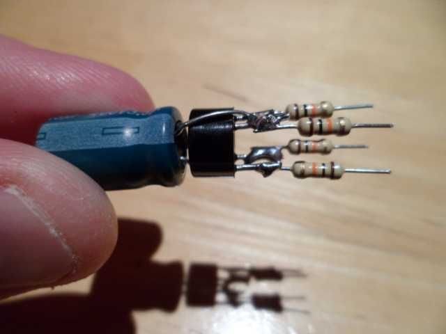
The cable on the existing tungsten string of lights is chopped about a foot (300mm) from the plug and the two wires coming from the plug are soldered to the resistors that are connected to the rectifiers AC input pins (usually marked with a small squiggle). The two wires going to the lights are connected with one going to the resistor connected to the rectifiers positive (+) pin and the other going to the resistor connected to the rectifiers negative (-) pin.
At this point it's a good idea to mark which of the wires is connected to the positive side as that will affect the direction the LEDs are plugged into the string.
Note the use of a cable tie and pen to keep all the wires apart. This is because we are going to pot the whole assembly in fast-setting two part resin to make it electrically safe.
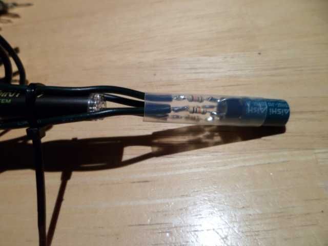
In this picture I used a bit of heatshrink sleeving to act as a potting tube, and ended up using two bits since I didn't have one long enough to cover both the (unnecessary) capacitor and the rest of the assembly. Ideally you would find a long thin plastic sleeve or container with a closed end so that there was plenty of room to pot the circuit deeply in resin.
This is a really tricky bit as you need to keep the wires well apart but still leave room to drizzle resin in around the components.
I recommend using two-part fast setting (about 5 minutes) resin, like Araldite or the many alternatives. I tend to mix it in disposable plastic shot glasses with wooden coffee stirrers that can also be used to drizzle the resin in.
If you use a larger sleeve/cap than I did then you can fill it part-way with resin and then plunge the whole circuit into it so it flows up and around the circuitry.
The resin tends to flow well around the components but if you do use the fast setting resin you may find 5 minutes just a bit too fast. If in doubt use the slower setting resin and have patience. Resin has a knack of getting everywhere, so do the potting in a suitable work area.
If it does go wrong then just start again. The components are cheap and it's better to end up with a safe power supply than a bodged one.
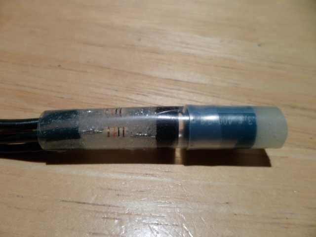
And here it is potted with the components visibly well spaced to avoid internal short circuits. The resin is acting as an insulator and modest strain relief for the wires.
Don't plug it in at this point as the current is so low that the tungsten lamps will not even glow, and instead the resistors will be getting hotter than normal.
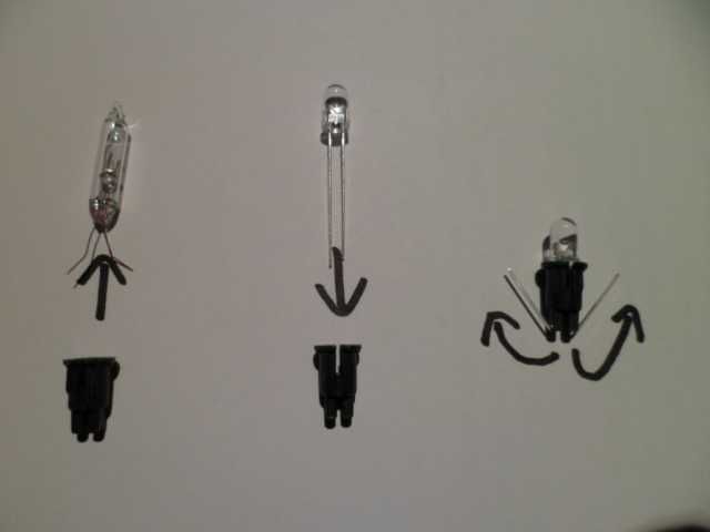
Now we start to swap the tungsten lamps for the LEDs, starting with just one. Remove the original tungsten lamp from its holder as shown and drop your choice of LED in its place. I strongly recommend the high brightness types for best effect. Push the LED fully against the front of the holder and fold the leads back along the side as shown above.
If you scavenge a highly desirable LED from somewhere and it doesn't have long enough leads, you can solder on extension leads so it can be used.
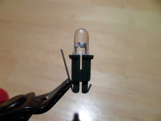
Carefully crop the bent LED leads so that they do not extend above the contact area of the base. I like to use a fine pair of snips and rest them on the ledge at an angle to get a consistent length.
If you crop them too short they may not make a reliable connection, and if you leave them too long they may prevent the LED going fully in.
IMPORTANT! Make sure no leads are left uncut as it will result in live pins sticking out of the lamp sockets when they are pushed in!
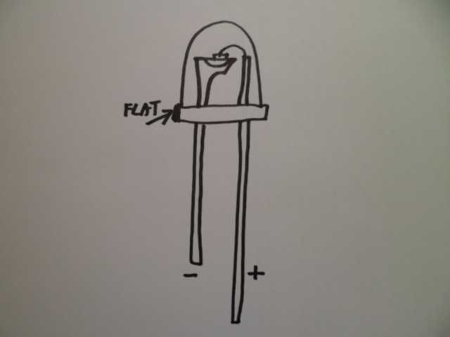
For reference MOST of the LEDs commonly available have the internal anvil shaped reflector inside them connected to the negative pin. It's important to ensure the LEDs are inserted into the string the correct way round as putting them in the wrong way round may destroy them.
I find it best to do just a few LEDs at a time so I can see if I have put one in the wrong way round, got a faulty one or not inserted it correctly.
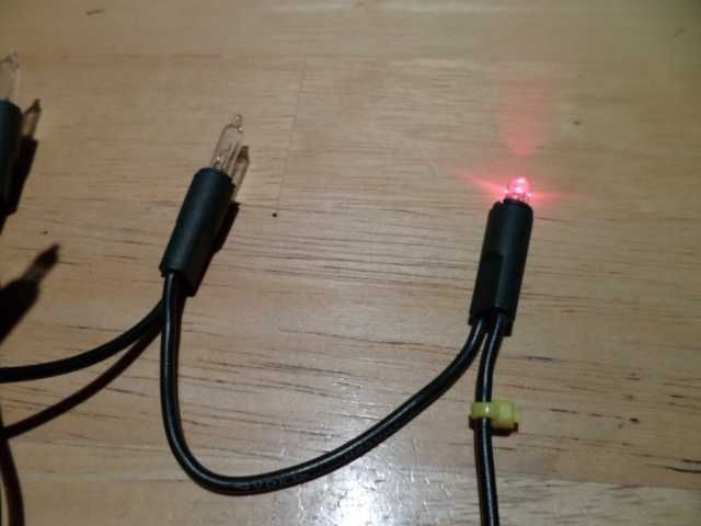
Note how I have marked the positive side of the string with a cable tie. All the LEDs positive connections will point towards that.
Don't leave the set lit too long with a lot of tungsten lamps still in it, as it will make the resistors run hotter. You can see that none of the old tungsten lamps are glowing at all while the red LED is lit. This is because the super-low current the set now uses is not enough to make them glow.
Now just work your way along the set from that end changing a few lamps over at a time. It's strangely therapeutic swapping in the LEDs.
If you wish you can make a little polarity dot on each holder to make swapping LEDs easier later on.
And soon you'll have a complete string of LED lights that can be swapped about and changed as desired when you stumble across new LED styles or colours (just remember to note the polarity before swapping them). You can also scavenge press-fit caps for them from other sets. If the caps are too loose on the bare LEDs then you can add a couple of layers of clear heatshrink sleeving round the LEDs to make them a press fit. A tutti-frutti style mish-mash of random colours and caps is strangely pleasing.
If you want to make standard lens style LEDs wider viewing angle you can do so by "cracking the ice" on them. This is where you carefully crack off the end of the lens with a pair of suitable cutters. Just make sure that you don't cut right down into the LED chip itself or expose the internal (live) metal connections. Also note that the end of the LED you're cracking off usually shoots across the room like a ricocheting bullet! Make sure you don't hit anyone with one! The cracked ice LEDs have a very crystalline effect that shoots the light out in all directions.
If you do use a random mix of styles and colours then you can pretty much guarantee that NOBODY ELSE in the world has a set of lights like YOURS.
And here's the best bit.... The whole set of lights now consumes less than a single watt of power! That means the whole string uses LESS energy than just ONE of the original lamps!
If you leave them on 24/7 they will consume much less than a single dollar of electricity in a year.
The fact the LEDs are being run at a fraction of their rated current means that they will last a VERY long time without losing efficiency.
Back to main project index.