HACK A FIBRE OPTIC DISPLAY.
Fibre optic lights like the one on this page have been about for a long time. They were originally made using glass fibres illuminated by a candle shaped light bulb, but these days the fibres tend to be plastic with a focused low voltage lamp as the light source.
This project involves the cheap gimmick fibre sprays that are available in the UK from "one pound stores" which would probably equate to "dollar stores" in the USA. They tend to be battery powered and have a few flashing coloured lamps inside. It's a complete waste of a good bunch of fibres, so here's a little mod I did to convert one to LEDs and make it run directly from the mains.
It consumes only a few watts and is a "reactive" load, so it can be considered as being zero-power. The LEDs should have a life time of about 100,000 hours continuous, although some of the cheaper Chinese LEDs are somewhat unpredictable in their lifespan.
If you decide to attempt a similar conversion to one yourself, then be very aware that the circuit operates at mains voltage, so extreme care must be taken in construction to avoid fire or injury.

Here's the light in it's original packaging. Isn't it amazing that you can buy this for just one pound.

Inside are three self flashing lamps with small bi-metallic contacts inside. They pulse and flash irregularly, making the fibre optic spray pulse in a rather vulgar manner.

The circuitry is a basic mains dropper that uses a capacitor to limit the amount of electricity that can flow on each half of the mains AC cycle.
The resistor is there purely to limit the inrush and transient current, and a good average value could be 220 ohms at 1W. Although the power dissipation is a fraction of a watt, the higher wattage resistors are much more robust and handle current transients well. The 1 megohm reistor across the mains input is to discharge the capacitor when the unit is unplugged to avoid getting a nip from the pins. The value is high to keep the dissipation of the resistor low, but it will rapidly drop the charge to a safe level when the unit is disconnected.
The bridge rectifier is a general purpose unit rated for the mains voltage. In this case it's a 600V unit to provide headroom.
The electrolytic is just there to soften the mains ripple. A zener diode (1.3W) is across the capacitor and LEDs so that if the LED circuit goes open circuit, the voltage across the electrolytic capacitor won't float above it's rating.
Finally, the LEDs themselves are just wired in series. This circuit can drive up to about 40 LEDs in series if the electrolytic and zener are adjusted accordingly, but for this application it was found that seven LEDs were just right for illuminating the end of the fibre bundle efficiently.
If your mains voltage is 120V, then you may need to use a larger value capacitor, although the circuit will work well as shown.

In the design of the PCB, a circle is made to match the diameter of the existing base, and some patches of grid are dropped on to help with the alignment of the three existing fixing holes.
The existing base is laid on the artwork and the holes marked through onto the template. The data is then transferred onto the PCB design.

The circuit board was designed on Boardmaker 1 which runs on a small industrial DOS box. It boots within seconds from it's flash disk, is silent and never crashes!
The components are designed to be placed on the copper side in surface mount style, so that the PCB itself forms the base of the unit. A sub PCB holds the LEDs up close to the base of the fibre bundle. There are two LED PCB's included in the design for colour experimentation.
Apart from the base fixing holes, there are two more for a cable tie as a cable strain relief.

On the left is the laser printed translucent artwork which is used to expose a photo sensitive layer on a copper laminated PCB.
In the middle is the exposed and chemically developed PCB ready for etching.
On the right is the etched PCB with all the surplus copper removed, and it's now ready for drilling, cropping and loading with components.

The components are on and the links made to the LED sub-board. Note the two M3 bolts being used as support pillars for the LED PCB. It's important to give a good clearance from live tracks to these, or for extra safety they could have been plastic bolts.
The only genuine surface mount component is the rectifier which is readily available in this format. The other components have been adapted for surface mount use by bending their leads appropriately.
The surface mount rectifier is different from most through hole rectifiers in that both the AC input pins are at one side and the DC output pins are at the other. It makes it much easier to design the PCB with good track clearance when it's configured in this manner.

The mains lead is connected to the PCB and locked in position with a cable tie after being threaded through a small hole made in the plastic casing. The LEDs on this unit are bright turquoise and their PCB is mounted at the most appropriate height by virtue of the adjustable nuts on the support bolts.

The cable is fed back through the case and the PCB assembly screwed into the bases fixing holes. The only part of the PCB now exposed is the blank side.

This is the unit lit up. It's consuming virtually no power, but is bright and vibrant. No heat can be detected at all.
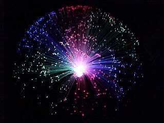
And here's the technicolour version with two red, two green, two blue and an orange LED.
I've done a white version too and it's very neat.

This is a plug-in LED night light that was part of the inspiration for the fibre spray. The main differences are the very low 1 ohm series resistor at the input which is presumably intended as a crude fuse, a surprisingly small 250 VAC 330n capacitor and a photo sensor circuit that simply shorts out the LEDs to turn the light off! Yes I did say it shorts them out...
The unit theoretically takes MORE power when it's not lit!
There's no zener across the capacitor in this circuit. If the LED panel goes open circuit, then the electrolytic will be charged up well beyond it's design rating and could go POP! (cool)
These little night lights can be hacked to make them a lot nicer by replacing the three yellow LEDs with five high output blues or whatever you want. The circuit board has the space for five LEDs. The light sensor circuit can be disabled by chopping the transistor and adjacent 1/8th watt resistors out.
When adapted with the new LEDs and the original tacky acrylic shell lens is removed, they can be plugged into a standard wall socket and will illuminate the wall above with a wash of light that goes right up to the ceiling.