Build a colour changing LED floodlight.
I'll guess most of us have seen the 150W or 500W halogen floodlights that are so cheaply available for outdoor lighting. Their cases are perfect for building a waterproof LED floodlight as shown in this project.
Although I've designed the circuit board to be compatible with my colour changing controller, it can either be used as a red, green and blue colour mixing panel or as a single colour panel. The use of a single colour could make it useful for low energy solar powered lighting or even as red/blue hydroponic grow lights.
The superflux LEDs are great to work with since they have four pins that make them sit level on the PCB. They also have very good output and beam control. You can get them quite cheaply from online sellers or by using search keywords like "100pcs superflux LED" on eBay. The ebay LEDs tend to be a bit variable in quality, but are generally fine for personal projects and cost a fraction of the high profile brands.

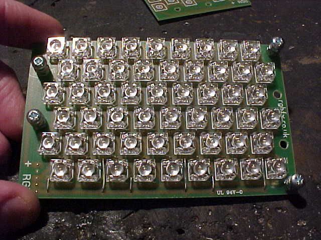
Here's the circuit board. I've had a batch manufactured to save having to etch your own. It's fully RoHS compliant and is designed to fit into a 150W halogen floodlight case. It holds 54 superflux LEDs, either as 18 of red, green and blue for colour mixing or all one colour. You can use any of the standard square, four pin, single chip, superflux LEDs regardless of lens size.
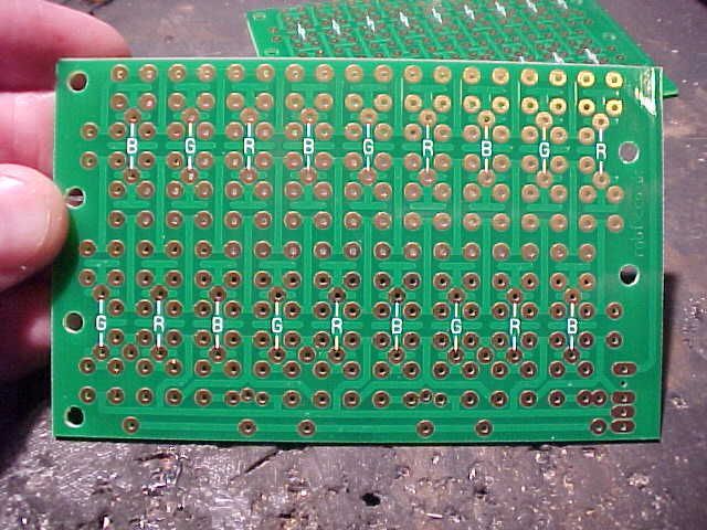
The copper side has been designed to dissipate the heat from the resistors over a large area by means of extra track fins. The resistors also mount on the back for neatness and to help keep radiated heat away from the LEDs.
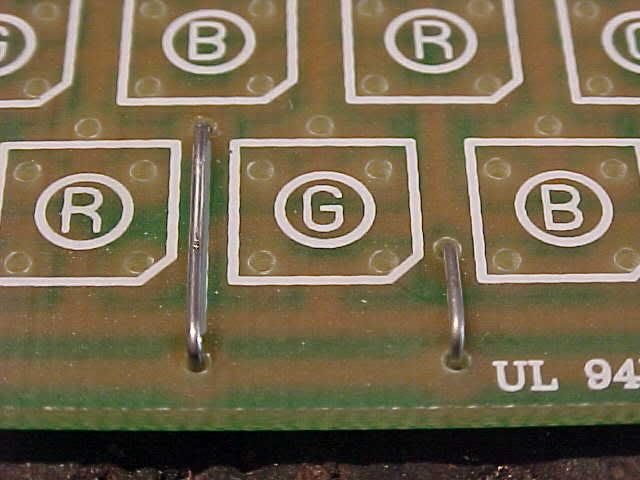
We start by mounting the six links. I could have made the board double sided, but it didn't seem worth it for so few links.
Then we mount the red LEDs noting the polarity chamfer on one corner and lining it up with the matching chamfer on the PCB component image. Resist the temptation to put all the LEDs on at once if you are using red, green and blue LEDs. Mixing them up is a bit of a nightmare.
Apparently some of the Chinese Ebay suppliers are shipping LEDs with reversed polarity, so before you solder all your LEDs in it is well worth checking that the polarity chamfer does indicate the negative side. You can either use a 9V battery and a resistor, or get a dedicated LED tester which is available quite cheaply on the Internet.
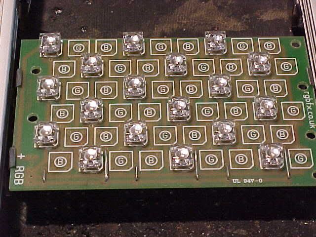
I always solder two diagonally opposite pins on each LED first. Then once I've done the whole board that way I go over them again doing the other two pins. This reduces the thermal stress on the LEDs compared to soldering them all at once. I do recommend the use of traditional lead based solder as opposed to the dreadful lead free stuff that is being forced on us by misguided eco hippies.
Then mount the green and then blue LEDs in the same way until the board has all its LEDs fitted.
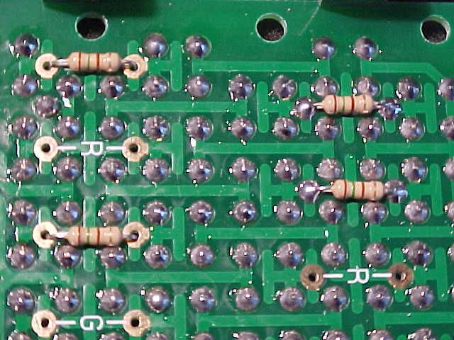
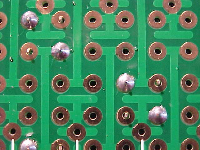
The resistors are mounted on the back of the PCB, so bend the leads and cut them quite short so they just poke through the other side of the PCB. The actual resistor values will depend on your choice of LEDs, but typically the red might be 220 ohm and the green and blue 150 ohm. The board is designed for operating the LEDs at 20mA. Higher currents are not recommended.
The LEDs are wired in series multiples of three for 12V use.
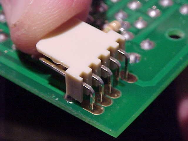
The board is designed to take a small Molex style connector on either the front or back, but you can also solder wires directly to the pads.
If you're making a single colour panel, just common the red, green and blue channels to light the whole panel.
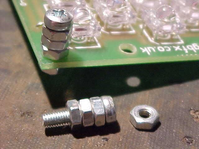
The mounting hardware is just short M3 (about 1/8" diameter) bolts with three nuts threaded on as spacers and one at the back to attach to the PCB.
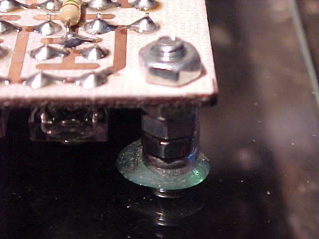
A drop of two part resin is put on the heads of the mounting bolts and the circuit board is then placed squarely on the floodlights glass front. Once the resin has set the PCB can be removed from the glass if desired, leaving the spacer bolts attached to the glass. It's a good idea to clean the glass and bolt heads with a solvent before gluing them together. I put six mounting holes on the PCB, but you only need to use three or four. They are spaced quite oddly due to the need to keep the PCB as small as possible to allow it to be used in a wide range of housings.

Heres a finished module with the red, green and blue channels at low intensity to avoid swamping out the camera.
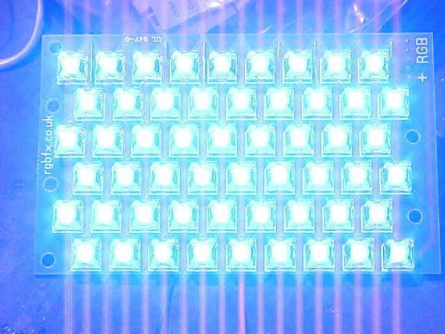
And here's a version with all blue LEDs at full output. Not comfortable to look at!
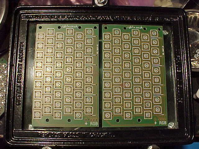
For larger lights and higher output you can mount two of these modules in the larger 500W style floodlight housing.