MAKE AN RGB LIGHTING CONTROLLER.
This is a very versatile RGB controller that uses a tightly programmed microcontroller to pack a lot of features into a small affordable kit. This module can drive up to 5A per colour at up to 30V to drive surprisingly large arrays of LEDs. If you're looking for a stand alone LED color changing controller then this might be just what you're looking for.
As a kit it's a very easy module to build due to the small number of components, clear markings and large chunky pads and tracks. I've deliberately chosen good quality components for this module including professional quality rising clamp terminals, beefy MOSFETs with a low on-state resistance and the chip is supplied with a good quality gold-contact turned pin socket. Fixing hardware for mounting it in your chosen application is also included.
These modules are now in use in almost every country in the world in a diverse range of applications that include prominent themeparks, nightclubs, trucks, ships, television and film productions, architectural features and moodlights. I get a lot of repeat orders for these kits, and you can't get better praise than that.

Here's a picture of the complete assembled module ready to go. As you can see it's a fairly straightforward design and you should be able to assemble it quite quickly. Here's a complete step by step assembly guide.

This is how the kit is supplied. Note that the two SIL resistor arrays are in the anti-static foam with the chip, socket and MOSFETs. This is to give greater protection to their pins in transit.

We start by soldering two wire links in. I could have made the PCB double sided to get rid of these links, but it's much easier to solder, modify and fix single sided boards. The links can be a bit of any suitably sized solid core copper wire. I strongly recommend the use of traditional flux cored lead/tin based solder. Although the manufacturing industry is required to use lead-free solder this regulation does not apply to hobbyists and specialist applications, Lead solder flows better, makes a better joint, and has a less corrosive flux making it a much better choice for home use.
Although this is an easy kit to assemble, I do recommend some soldering experience beforehand, and if you are already experienced then you can skip this next bit.
Soldering is easy. You touch a heated soldering iron to both the pad and the component lead to be soldered to bring them up to heat, then apply the solder to them so that it melts and joins them together physically and electrically.
NEVER carry melted solder on the iron tip and then try to blob it onto the lead and pad like glue. It doesn't form a good joint. Electronics grade solder has cores of flux that melt with the solder and help clean the surfaces and mate the solder to them. If the solder is melted onto the iron then the flux evaporates before it can do its job.
Timing is also relatively critical since you don't want to burn the pad or damage the component. You'll soon get a feel for the way the solder flows and just kinda get a feel for the correct amount of solder to feed onto a joint. It really is all down to practice and experience.
A clean soldering iron is essential and you can get stands with either a damp sponge or a metal "scourer" built in that can be used for wiping any excess solder or crud off the tip of the iron. The tip of the iron should be clean and shiny. If it is black and pitted then get a new tip for your iron as a clean tip is essential for proper transfer of heat.
If in doubt, practice on another PCB first until you are comfortable with soldering.

Next we solder in the first of the resistor SIL arrays. If your PCB doesn't have this then you may have a different version that uses individual resistors which you can find HERE.
This component has eight pins and can be fitted either way round. It contains four separate 1000 ohm resistors. The resistors are connected between the processor and the gates of the output transistors. They serve to limit current in the event of a fault and also allow the use of other types of transistor.

Next is another smaller SIL resistor array. This one contains four 10,000 ohm resistors and is used to keep the MOSFETs turned off while the processor boots up. Normally a SIL like this would have to be installed into the PCB in a specific direction, but in this case you can put it in any way round.

Now we install the socket for the processor. This has an indent at one end that should be aligned with the matching indent on the PCB graphic. This is to help identify the correct way for insertion of the processor chip later. If you solder the socket in the wrong way round then just leave it, but try to remember to insert the processor chip according to the PCB graphic.

Next we install the two little blue decoupling capacitors. These can be inserted either way round and their function is to reduce the risk of external glitches and power transients from affecting the processor. In reality the circuit would work without one or even both of them, but it's good design practice to include them anyway.

Then comes the voltage regulator, which is a three pin device and must be inserted the correct way round. The flat side goes towards the processor socket as shown. The function of the regulator is to provide a stable 5V supply for the processor regrdless of the input voltage to the controller in the range of about 9V to 30V.

Now for the power indicator LED. This is mounted with its longest lead going into the hole nearest the "+" symbol, and the flat on the LED package at the side marked "LED". Its function is to show you have a 5V supply present on the controller.

Next we install the two buttons. One is for selecting the program and the other is for the options. They are a gentle press-fit into the holes to keep them in place while you solder them.

Next in is the polarity protection diode that helps protect the circuit if you connect the power to it incorrectly. One end of the diode has a silver stripe on it and this must match the stripe on the end of the PCB graphic.

Now comes another polarised component and this one MUST be inserted the correct way round or it may go POP! It's the power supply smoothing capacitor and the long lead goes to the "+" symbol as shown. The job of this component is to ensure a steady supply of power to the processor when the power supply is unstable or electrically noisy. It can also be mounted lying down on it's side with the leads bent at right angles if desired.

Now use a pair of narrow nosed pliers to bend the MOSFET leads as show, so they fit into their pads on the PCB. The pads are deliberately spaced a bit wider to allow the use of thicker pads and tracks.

Now solder the MOSFETs in, making sure you install them the right way round.

Next we install the terminal block for connecting external wires to the controller. I could have used a MUCH cheaper connector, but this professionally rated component is much easier for connecting and disconnecting wires. It uses a rising clamp cage system instead of the more common metal tongue system.

And if you wish, you can flow some extra solder along the high current carrying tracks to beef them up if you intend to use the module with a high load. I've left the solder-resist coating off the high current carrying tracks to allow for this.

Now we install the processor chip. This is a PIC microcontroller programmed in machine code to cram as much functionality into a small chip as possible. It must be inserted the correct way round with its indent matching the one on the socket and PCB graphic. Take care to ensure that all the pins are sitting into the socket correctly before pushing it fully in.

Finally, before powering the controller up, I recommend that you insert the little nylon support feet that can be used as simple feet to keep the PCB from shorting out on loose metalwork on your bench, or to permanently mount the module in a finished application.
The controller is connected to your power supply and LEDs as follows:-
"B" The output for the blue LEDs. Pulls down to 0V to illuminate the LEDs.
"G" The output for the green LEDs. Pulls down to 0V to illuminate the LEDs.
"R" The output for the red LEDs. Pulls down to 0V to illuminate the LEDs.
"-" The circuits negative (0V) supply.
"+" The circuits positive supply from 9-24VDC.
"+" Common +ve connection for the LEDs.
The power supply is chosen to match the configuration and number of LEDs you're using. A standard plug-in 12V DC power supply is fine for most applications. A regulated supply is best since the unregulated ones can sometimes float up to a higher voltage when lightly loaded. If using a cheap multi-voltage unregulated adapter it might be worth setting it to a lower voltage like 9V.
This type of controller does not limit the output current, so you MUST use a resistor in series with each LED or group of series LEDs as shown above. The above example is based on a 12V supply and three LEDs in series per circuit. Typical resistor values for three LEDs in series on 12V might be:-
150 ohm for blue or green LEDs.
270 ohm for red LEDs.
Although you can use high power LEDs with this controller, you must remember to use suitable resistors in series with the LEDs and the resistors themselves can get very hot. If using high power LEDs I recommend sticking to the 1W chips since they are easier to heatsink, and try to wire three LEDs in series per resistor on each channel for 12V use. The combined RGB versions often have a six terminal version to allow series connection of the LEDs like this.
My own preference is to use large arrays of standard LEDs to help spread the heat dissipation from the LEDs and resistors over a larger area. You can find various LED panel designs on my website that are designed for arrays of the square superflux LEDs.
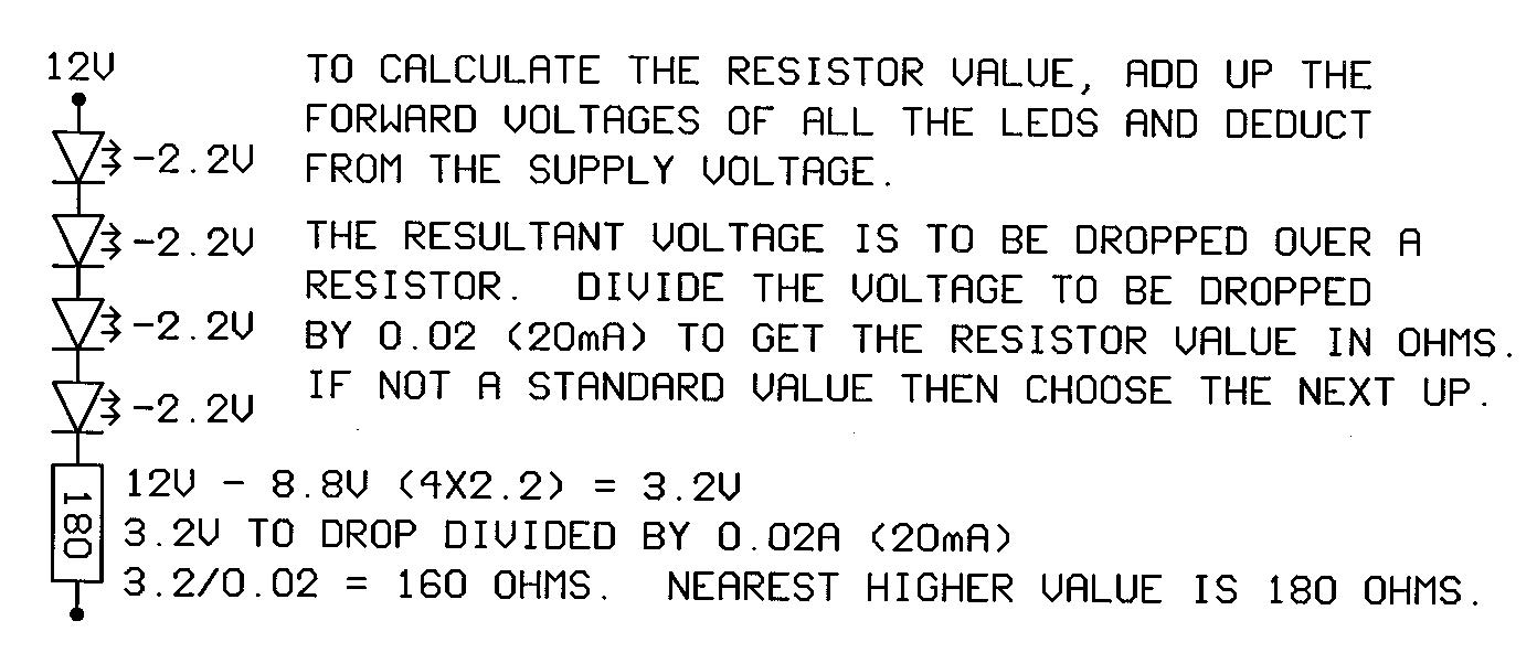
Click the image above to see a graphic guide to choosing resistor values for LED circuits.
View the control chips data sheet.