MAKE AN RGB CONTROLLER.
The original and still the most versatile RGB controller that uses a tightly programmed microcontroller to pack a lot of features into a small affordable kit. This module can drive up to 5A per colour at up to 30V to drive surprisingly large arrays of LEDs. If you're looking for a stand alone LED color changing controller then this might be just what you're looking for.
As a kit it's a very easy module to build due to the small number of components, clear markings and large chunky pads and tracks. I've deliberately chosen good quality components for this module including professional quality rising clamp terminals, beefy MOSFETs with a low on-state resistance and the chip is supplied in a good quality gold-contact turned pin socket. Fixing hardware for mounting it in your chosen application is also included.
These modules are now in use in almost every country in the world in a diverse range of applications like limousine lighting, mood lights and nightclubs. I get a lot of repeat orders for these kits, and you can't get better praise than that.

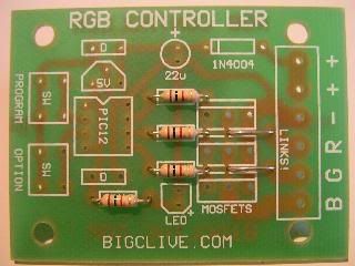
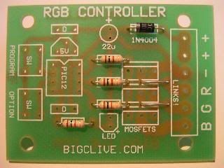
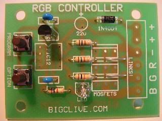
Here's a picture of the complete assembled module ready to go. As you can see it's a fairly straightforward design and you should be able to assemble it quite quickly. Here's a complete step by step assembly guide.
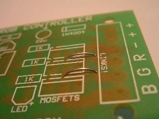
The first things to install are the links. These are important. Without them the red and green channels won't work!
They're simply offcuts of wire soldered in to form a small bridge.
If you are experienced at soldering then you can skip this bit. If you haven't soldered before or have just done a little then here's a simple guide.
Firstly you can forget the "lead free" solder that is being forced on us by the eco-hippies. It's crap. Although the PCB and most components are suitable for lead free solder I don't recommend it at all. Use traditional tin/lead electronic grade solder with a flux core.
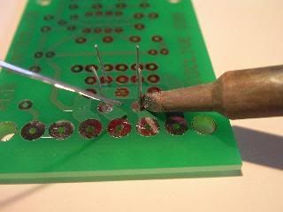
The principle of soldering is as follows... You heat both the component terminal and track simultaneously with the tip of your iron (as shown above) to bring them up to a temperature where the solder will melt. Then you apply the solder to the joint and remove the iron tip after the solder has flowed around the joint. It sounds simple (it IS simple) but does require a bit of practice to get the technique right. The worst thing you can do is hold the iron on too long, since this can damage the components with excess heat.
My preferred soldering iron is the common Antex XS25. I strongly recommend the standard spring-like soldering iron stand too. It has a spring to park your hot iron in, and a small damp sponge for wiping the tip on.
When you first use a new soldering iron it's important to tin it by applying a bit of solder to the tip as it heats up. As soon as the solder melts it primes the surface of the iron and makes it perform well. If the tip of the iron is covered in burnt-on crud then it won't take the solder well and soldering will be hard. If the tip can't be cleaned easily then get a new tip (bit). Don't file the tip! Most irons have a layer of iron on a copper core and filing will remove this making the iron tip burn up quickly.
Never carry solder over to the component joint on the iron. It's very important that the solder is directly applied to the hot component leads, since the flux that is released as the solder melts is used to clean and prime the surfaces to make the solder flow onto them well. If you carry the solder over the flux will evaporate and you will end up with a "dry" joint that looks dull and doesn't make a good connection.
If you've never soldered before then try getting a bit of a material called vero board which is punched with holes and has copper strips on the back. Get lots of bits of wire and just solder away until you feel comfortable with your technique.
Good soldering ability is all down to experience. The more you solder the better you'll get. Soon you will find that you can hold the iron, PCB, component and solder with only two hands. Amazing. :)
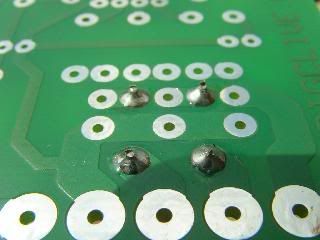
Here's the result after soldering. Shiny solder joints that wick up to the component lead. After soldering each joint, snip off the excess wire at the top of the joint.
If you make a mess of the joint then one of the best things for removing excess solder is called desoldering wick. It's basically a copper braid covered in resin that soaks up solder like a sponge when it's placed on the joint then heated with a soldering iron. Hopefully you won't need any!
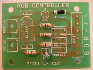
It's a good idea to fit the components in order of size, so fit the resistors next. These are all the same value 1000 ohms (1k) and can be put in any way round in the spaces marked 1k as shown above.
If your PCB doesn't have positions for these resistors then you may have a newer version that uses SIL array resistors which you can find HERE.
Three of the resistors are used to connect the control chip to the control pins (gates) of the MOSFET transistors, and one resistor is used to limit the current to the power indicator LED.
Next fit the diode. This is a common 1A rectifier diode and is used to protect the circuitry from wrong connection of the supply. It only allows current to flow in one direction, so must be fitted the right way round.
It's space has a band at one end that matches the band on the body of the diode. the diode is listed on the PCB as a 1N4004 but any diode in the 1N400X range may be used. You probably have a 1N4007 which has the highest voltage rating.
Next is the power indicator LED. This indicates when the circuitry has power and will only work if it's installed the correct way round. The longest lead is the anode and goes to the hole nearest the "+" symbol.
If you chop off the leads and then forget which pin is which, then there is a small flat on the body of the LED next to the negative lead. This corresponds to the flat side of the PCB symbol.
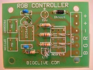
Next come the little blue decoupling capacitors. These are not polarised so can be fitted in any way round. Their function is to suppress any glitches or spikes on the supply that might cause the processor to misinterpret a logic level and do something weird.
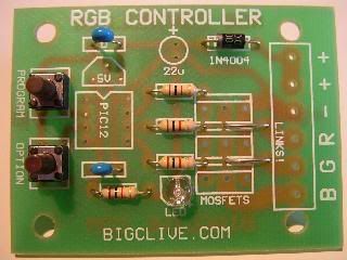
Next are the two push button switches. These are designed to push-fit into the PCB and are very easy to solder.
If desired the switches can be soldered on the back of the PCB. This will then allow the PCB to be mounted to the back of a standard switch blanking plate with the buttons protruding through the front for a simple but neat control panel.
The fixings and buttons have been lined up on the manufactured boards for this reason.
Now fit the little three pin voltage regulator making sure that it's the correct way round as shown above.
This clever little device (a 78L05) will accept any supply voltage between about 8V and 30V and put out a steady 5V for the processor.
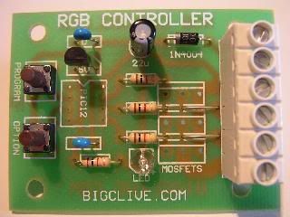
Two components are fitted in this picture. The 22uF electrolytic capacitor and the terminal block. The capacitor absolutely MUST be inserted the correct way round. Again the longest lead is the positive connection and a grey band on the case indicates the negative side. Double check the pictures to make sure you have it in the right way round. It's function is to smooth out any dips or transients in the main supply to provide the control circuitry with steady power.
The terminal block is easy to fit but has large pads so will require a fair bit of solder. Make sure the open side is facing outwards, since it'll be very hard to connect into if it isn't!
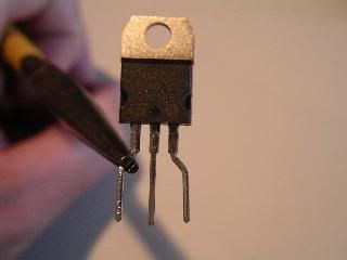
To allow for the high current tracks, the MOSFET pads on the PCB are spaced wider than their leads.
Use a pair of long nose pliers to bend the leads slightly to match as shown above.
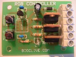
Then install the MOSFETs into the PCB as shown.
Finally fit the control chip. This probably came already clipped into it's socket, but if you like you can carefully remove the chip from the socket by carefully prising it out from both sides with a thin screwdriver. On the other hand you can just solder the whole assembly in as supplied. (Which is easier.)
There is a notch or indent on one end of the chip and a matching notch on it's socket. Make sure they're both aligned with the matching notch shown on the PCB graphic. If you do accidentally screw up and mount it the wrong way round, then simply unplug the chip from the socket and turn it round. As long as the chip is aligned with the PCB indent it will work.
This chip does all the serious work. It's a well featured microcontroller which I've filled to capacity with some awesome machine code to do all the smooth random colour changes. Check out the control chips data sheet to see what this little gem can do.
This picture also shows that the nylon spacers have been clipped into the holes at the corners of the PCB. Even if you're not screwing it to anything yet, you can still use the spacers as feet to keep the circuit board away from your bench and any loose metal bits that might be lying on it.
The controller is connected to your power supply and LEDs as follows:-
"B" The output for the blue LEDs. Pulls down to 0V to illuminate the LEDs.
"G" The output for the green LEDs. Pulls down to 0V to illuminate the LEDs.
"R" The output for the red LEDs. Pulls down to 0V to illuminate the LEDs.
"-" The circuits negative (0V) supply.
"+" The circuits positive supply from 9-24VDC.
"+" Common +ve connection for the LEDs.
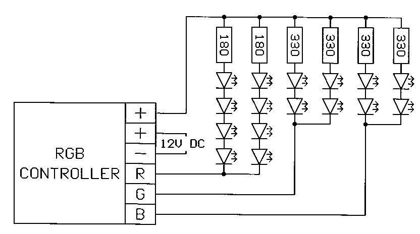
The power supply is chosen to match the configuration and number of LEDs you're using. A standard plug-in 12V DC power supply is fine for most applications. A regulated supply is best since the unregulated ones can sometimes float up to a higher voltage when lightly loaded. If using a cheap multi-voltage unregulated adapter it might be worth setting it to a lower voltage like 9V.
The resistor values shown above are just a rough guide to get you started. Each circuit of LEDs MUST have a current limiting resistor fitted to limit current flow to within the LEDs rating. This is usually 20mA (0.02A) for standard 5mm LEDs.
The red LEDs can usually be wired in series multiples of four on 12V as they have a forward voltage of about 2V. The greens and blues have a higher forward voltage and it's better to wire them in pairs as again shown above.
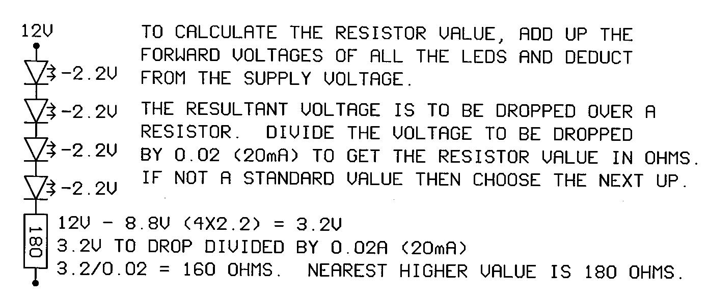
Click the image above to see a graphic guide to choosing resistor values for LED circuits.
View the control chips data sheet.
Want to etch your own PCB's?
Click here for the track and layout of this PCB in TIF format
(Including a simple three LED version)